40 Meter 4 SQUARE ANTENNA PROJECT. April/May 2022

All antennas up.
Flat across the band.
Base connections complete.
Coax connected up.
All conduit containing coax from antennas to the Box now finished.
Coax and control cables put in conduit first.
Junction box installed to join to shack cabling.
New underground CAT5e control cables pulled through.
5 posts in and removed Hytower antenna.
75 Ohm Coax cut to match 7.140MHz to go from controller to antennas
Radial plates made.
SO239 mounts bent to requirements.
SO239 mounting plates made.

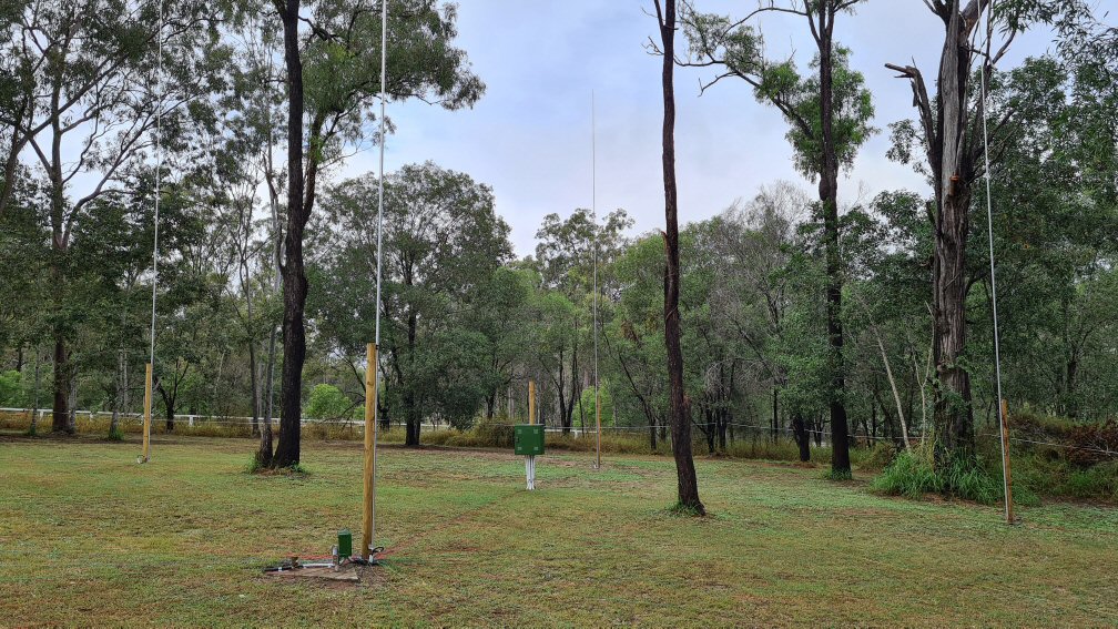
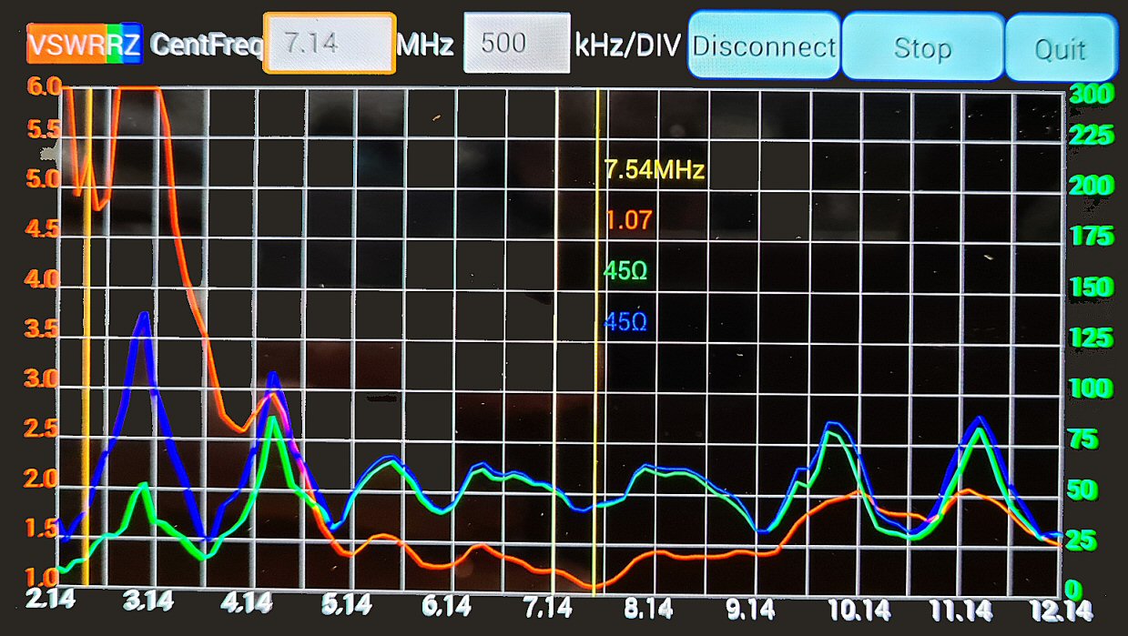
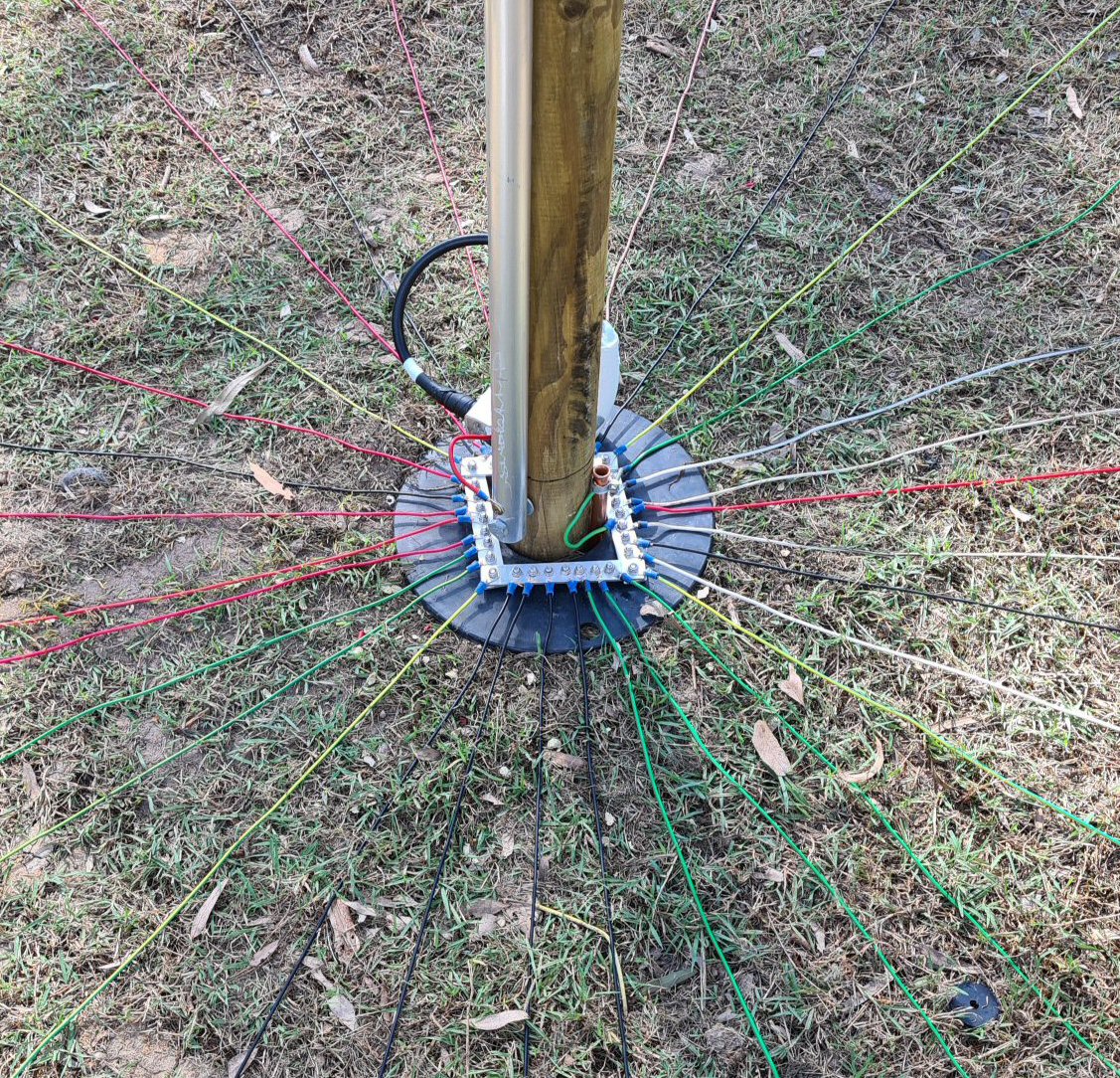
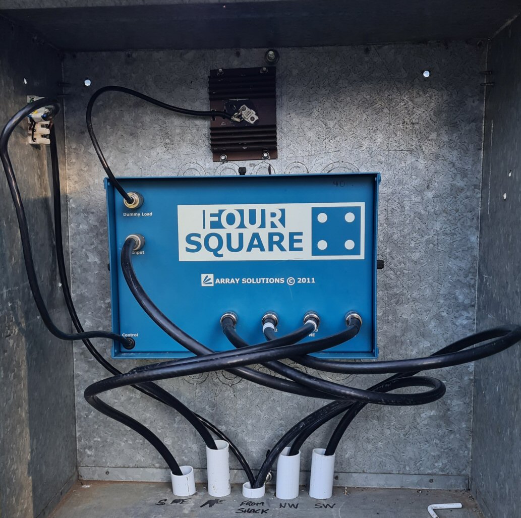
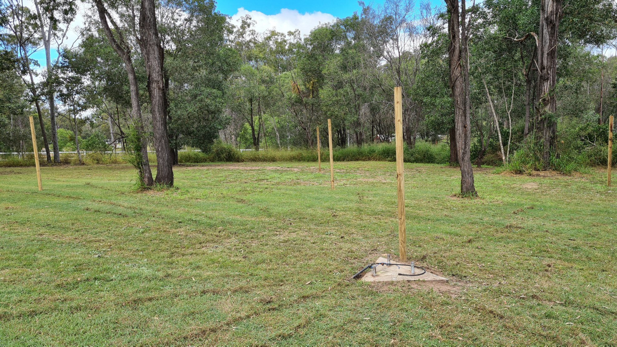
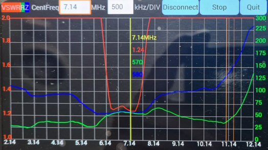
40 Meter 4 Square Antenna Specifications

Between posts: 10.5 meters

Antenna height: 10.240 meters

Radial length: 12 meters

Number of radials per antenna: 32

Single antenna ressonance: 7.080 MHz, 1.26:1, 51 Ohm.

RG-11 75 Ohm feed cables: Cut for 7.140 MHz

--

VSWR readings in shack on 7.100 MHz:

NE 1.31, 50 Ohm

NW 1.15, 50 Ohm

SE 1.24, 56 Ohm

SW 1.36, 52 Ohm

OMNI 1.76, 31 Ohm

28 MHz 5 element Beam and Tower erection. 14/11/2020

Tower up. 1.5 S points better than my TH6DXX.
Home Made Antenna - The Beta match.
Home made antenna - driven element insulators made from plastic.
Design is similar to the Hy-gain 28MHz antenna.
A 3000lb winch pulls the tower up easy.
Tower ready to connect

21 MHz Tower erection with the help of Ken VK4QH and Mark VK4FDAD - 28/9/2014

Tower Base
Tower Jig to hold tower
Tower locked in at base with chain from tower then through pulley at the jig point then to bull bar. Guys are attached to the tower and ground. A metal welded 'X' lets the tower sit nicely without rolling. A smooth reverse and the tower is up. Thanks for your help Ken and Mark.
Download movie of lift
Tower locked in position 2015.
4 Element and 3 Element 21MHz stacked. Jan 2018.

4 Element 6 Meter beam erected - 15/12/2018

6m Beam

EU Beverage antenna installed 17/5/2015

Many thanks to Ken VK4QH and Mark VK4FDAD for their valuable assistance.
Initial results are looking very good. I can now hear stations on 80/40m that were not heard in the noise previously.
Beverage coax end
Beverage wire held up with star pickets and 50mm water pipe as an insulator. Side fence is 312 degrees which suits nicely.
End of 80mtr run

USA Beverage antenna installed 27/6/2014 facing USA Short path

Making my own beverage boxes.

My new Hy-Gain Hy-Tower installation is now finished

Initial testing without 80/160m coil
Trench to the tower from shack
Relay, 80/160 coil fitted, and anti-static coil fitted.
160mtrs to 6mtrs including WARC. Nice.
Large coil added for 160m. Note 160m high and low taps at base
and 80m high and 80m low selection at top of coil.
Thick red wire shorts out coil for operation on 40m - 10m
Turning my Hytower into a 3 element Vertical Beam. With one relay wired normally closed and the other normally open, flicking the power on will swap directivity. The coils are used to give the element extra length and the relays short the coil out to make a shorter element. Extra elements are placed 1/4 or 1/8th wave from the tower.

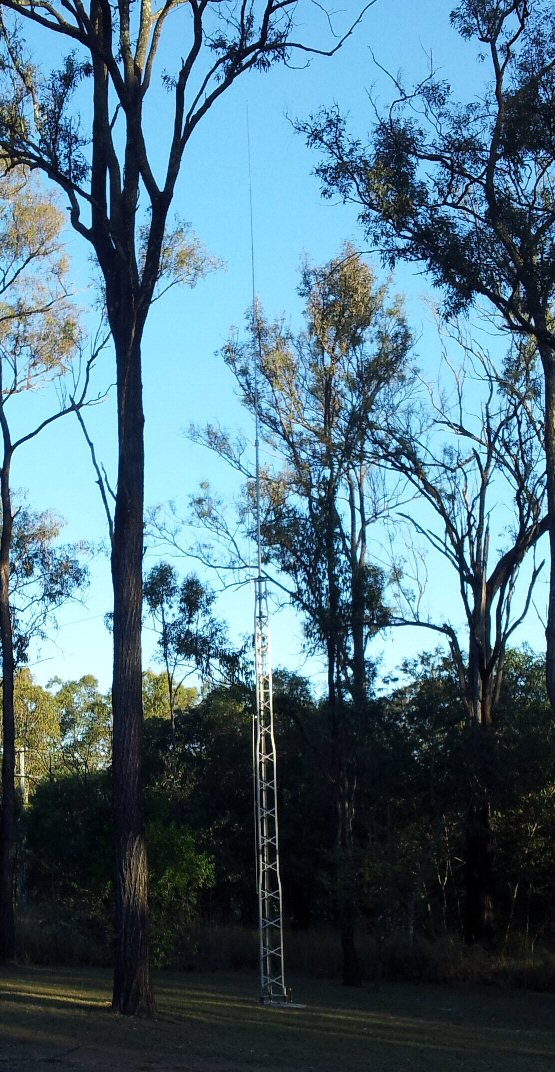
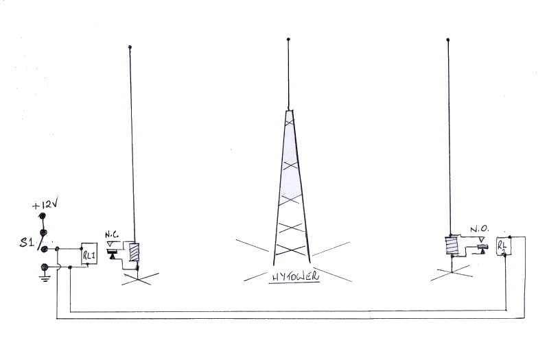
HYTOWER HYGAIN VERTICAL INFORMATION

  A B C D E F
Number of radials 16 24 36 60 90 120
Length in wavelengths 0.1 0.125 0.15 0.2 0.25 0.4
1.840 MHz 16.30 Mtrs 20.38 Mtrs 24.46 Mtrs 32.61 Mtrs 40.76 Mtrs 65.22 Mtrs
3.600 MHz 8.33 Mtrs 10.42 Mtrs 12.50 Mtrs 16.67 Mtrs 20.83 Mtrs 33.33 Mtrs
7.100 MHz 4.23 Mtrs 5.28 Mtrs 6.34 Mtrs 8.45 Mtrs 10.56 Mtrs 16.90 Mtrs
14.200 MHz 2.11 Mtrs 2.64 Mtrs 3.17 Mtrs 4.23 Mtrs 5.28 Mtrs 8.45 Mtrs
21.150 MHz 1.42 Mtrs 1.77 Mtrs 2.13 Mtrs 2.84 Mtrs 3.55 Mtrs 5.67 Mtrs
28.300 MHz 1.06 Mtrs 1.33 Mtrs 1.59 Mtrs 2.12 Mtrs 2.65 Mtrs 4.24 Mtrs
Spacing in Degrees 22.5 15 10 6 4 3
Total length of wire in Wavelengths 1.6 3 5.4 12 22.5 48
Power gain Db due to increased efficiency 3 3.6 4 4.7 5.2 6
Take-off Angle 30 30 30 30 28 24
Feed-point impedance with 1/4 wave radials 52 46 43 40 37 35
Radial end buried. YES YES YES NO NO NO
6 Pack with coax filters installed. Just add antennas ;-)

My 80/40mtr 1/4 Wave Vertical

Added a 7MHz trap to add the 80mtr band - 21/4/2012
I wound a 7Mhz Trap and attached it to the top of the 1st section (7MHz part). I then added an insulator into the 2" section and used very thin walled aluminium for the top section for resonance on the 80mtr band. The exercise was to allow use of the 80mtr DX window, which my Loop didn't.
7MHz trap was wound out of RG213. The trap will handle up to 1500W whereas a RG58 trap will only handle about 600W.
1:1 Ugly Balun wound on 4" plastic pipe using RG213.
Anti-Static Discharge coil added between driven element and earth.
The 25mm diameter conduit is 8 inches long and I used AWG14 copper enameled wire.
Resonant Radials for 80/40/10 mtrs are buried 2" below the grass. There are 36 radials.

Ground Mounted Vertical Antenna Notes for 7MHz and below

  • Correctly configured ground mounted vertical antennas for 7MHz and below will out perform horizontal antennas for DX work.
  • A horizontally polarized antenna is better for local contacts up to approximately 1000km.
  • A good ground plane is essential for a vertical to perform well.
  • A vertical antenna has a lower radiation angle than a horizontal antenna.
  • A good ground system has a critical angle of about 10 degrees, where a bad ground will give a higher angle of about 30 degrees.
  • Good ground systems have a low angle of radiation and greater field strength.
  • Bad ground systems have a higher angle of radiation and up to 4dB poorer field strength than an antenna with an excellent ground system.
  • Tuned radials (i.e. ¼ wave for example) are the best choice and ½ wave length radials will be an advantage over the ¼ wave.
  • The more radials the better, although 120 radials seems to be the maximum needed. At least try for 24 to 48 radials if possible.
  • If you haven’t got the room to lay the radials straight, then bending them around objects or trees is ok.
  • A horizontally polarized antenna at frequencies above 7MHz maybe equivalent to, but is normally a better performer than a vertical antenna.
  • A tin roof with about 20-30 degrees sloop makes an excellent ground plane when the vertical antenna is mounted on its peak.

Nissan Navara D22 Diesel - Stopping engine noise on HF

Engine noise on HF is mainly caused by the 70 Volts used to inject diesel in to the motor. Some noise is evident from the under dash fan and also the fuel pump. The Engine noise was so bad I had to wrap the wires in Aluminium foil and earth them to take away 80 % of the noise. I cable tied a piece of bare wire connecting all the foil together and then earthed the cable to the body of the car.

Modifying a 27MHz CB Ringo Antenna for 80–6Mtrs

Download the PDF document here.

A 27MHz Ringo has been collecting dust in the shed for years, and after successfully constructing a vertical for 6 meters, it was time to put the Ringo to good use.

The plan is to remove the ring and connect 4 x ¼ wavelength radials for each band. The center of the SO239 connector is connected to the 5.3 meter driven element via a short piece of aluminum. The driven element is already a 1/4 wavelength on 20 meters. A bracket was made from aluminum strip to bolt the radials to and was screwed to the existing earth bracket left over after removal of the ring.

A 50mm x 500mm pipe is hammered into the ground leaving 200mm above the ground for the base of the vertical to slip into. Radials were cut from 2.5mm diameter aluminum wire scavenged from old power line cable. Initially the 10 and 20 meter radials were bolted to the earth bracket. A random length of RG58 coax was run from the antenna to the shack where a dip meter coil was screwed on. One would have thought that 20 meters would have tuned/dipped perfectly being a 1/4 wavelength vertical. But not so. Adjusting the length of the antenna had no real effect on the reading of 18MHz dip.

After several failed attempts on other frequencies, the coax was tested resulting in – yes – a 18MHz dip. (It is interesting to note that the coax had little effect on resonance when the antenna was setup for a 1/4 wavelength on 28MHz, but played havoc when used for other wavelengths and/or bands). A new 27.85 meter length of coax was cut and terminated with PL259 plugs. This cable now dipped on the amateur bands and was duly plugged into the antenna. Hey presto, a perfect VSWR was obtained on 14MHz as expected. The length of coax cut is the only length of cable that is resonant on all HF ham bands. One could cut a single 1/4 wavelength piece to match one band but the aim here was to use all bands with one vertical.

Two radials for 7MHz were now attached and laid out across the ground. (The other two are yet to be cut). 10cm of each end was bent down and pushed into the soil to hold them in place till a proper burial can take place. Further testing confirmed the entire 14MHz band was 1:1 and 1.4:1 on 6 meters. With the aid of an ATU, all other bands were tunable including 80 meters. Yet to add is 2 more radials for 7 MHz, and radials for 21MHz. It will be interesting to see what improvements, if any, take place once they are in place.

The following table was used as a guide for measurements. Radials were cut using the measurements in the 1/4 wavelength column.


300 Wavelength
  FULL 5/8TH 3/4. 1/2. 1/4. 1/8. 1/16.
Freq 1.000 0.625 0.750 0.500 0.250 0.125 0.0625
52.000 5.769 3.606 4.327 2.885 1.442 0.721 0.361
28.000 10.714 6.696 8.036 5.357 2.679 1.339 0.670
21.000 14.286 8.929 10.714 7.143 3.571 1.786 0.893
14.000 21.429 13.393 16.071 10.714 5.357 2.679 1.339
7.000 42.857 26.786 32.143 21.429 10.714 5.357 2.679
3.570 84.034 52.521 63.025 42.017 21.008 10.504 5.252
1.825 164.384 102.740 123.288 82.192 41.096 20.548 10.274
Antenna length = 5.3mtrs

Building a 9 to 1 balun

Mounting the SO239 and fitting the balun.
Fitting into case and connecting bolts
Complete unit ready to use.