Contents of this page:
Updated 24/07/2025
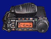
Hold down these buttons while turning the power on...
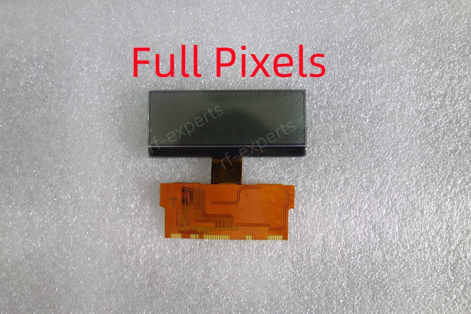
Full pixel screen.
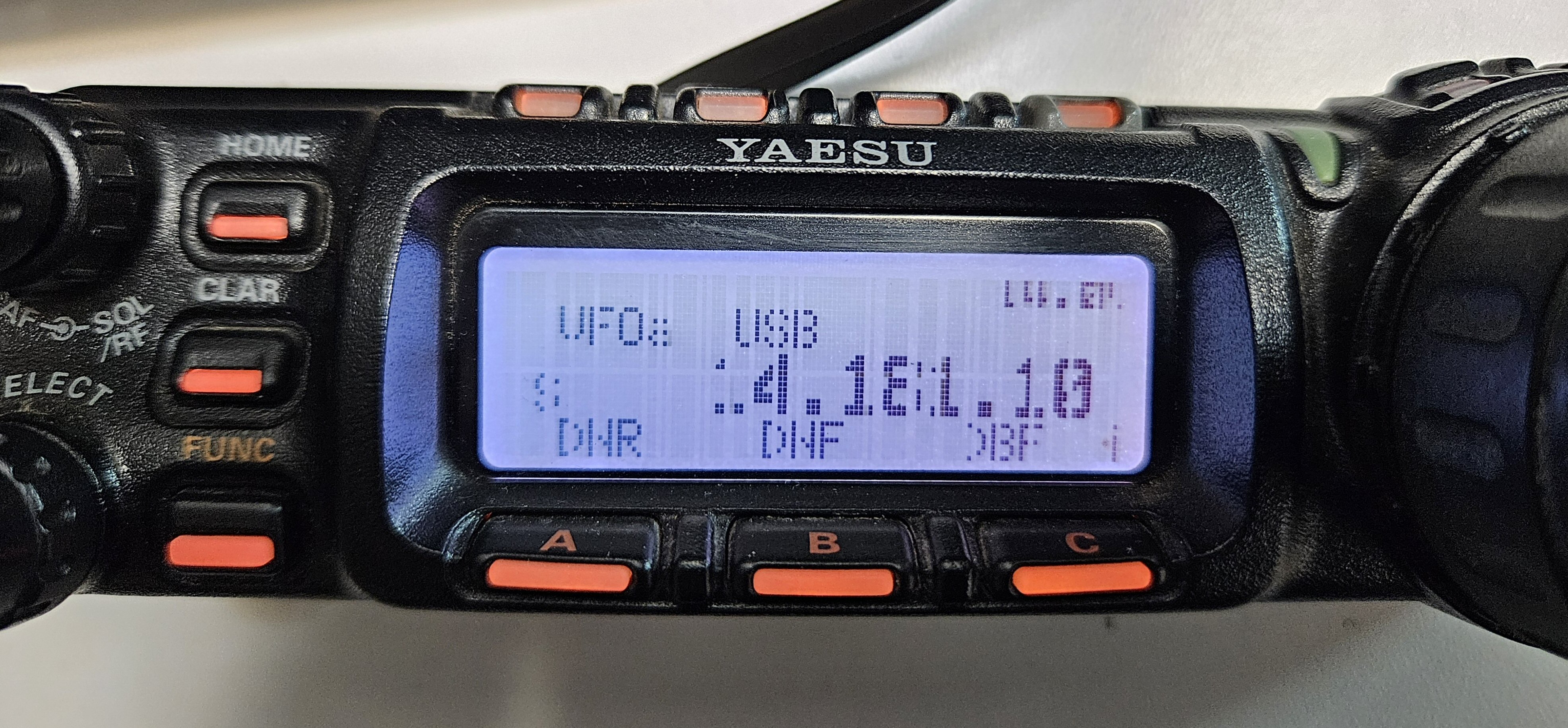
Display before replacement
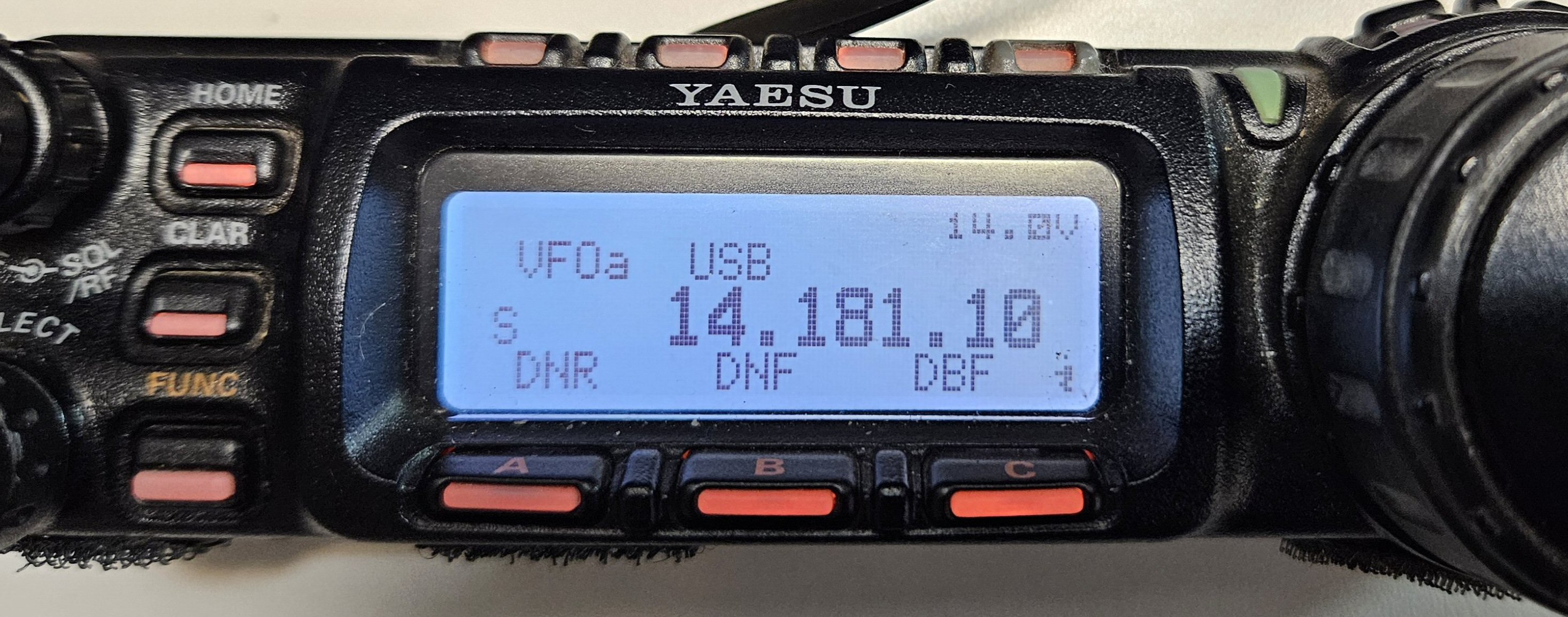
The replaced screen
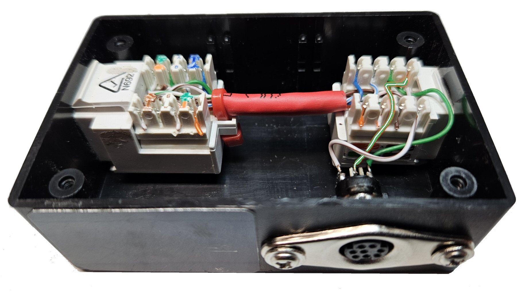
My home brew microphone/COM port adapter using 2 x Keystone jacks and mini din socket.
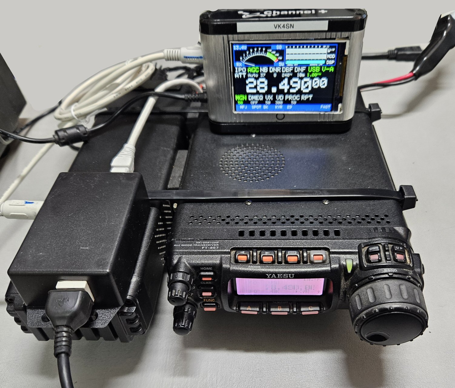
Tuner connected to the rear port and external display on mic com port.
NOTE: When using the mic COM port to connect to a PC, the COM port RS232 interface (as below) is still needed, or buy a USB to mini din COM port adapter.
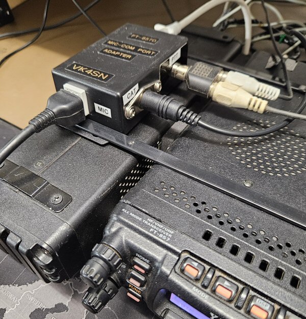
Upgraded the adapter to include a PPT for the foot switch.
The double outlet feeds to the foot switch and the other PTT's my SDR switch. I have since repaired my display and now the RS232 goes to the PC for the N1MM logging. With a microphone adapter, I can now use a headset with microphone.
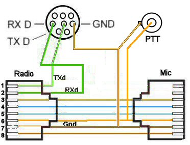
The Circuit Diagram
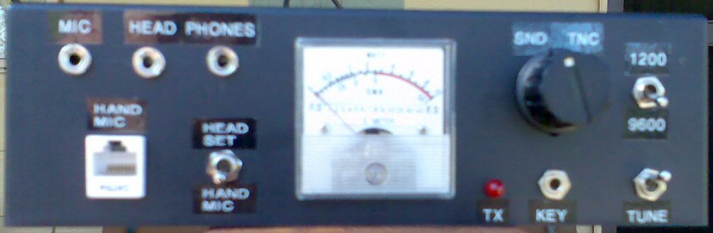
I wanted the flexibility to switch PC's, head phones, morse keys, etc. The project was built using readily available parts. I used a circuit from the AR mag for the sound interface and a simple RS232 interface for CAT control. I also wanted to have the ability to use headphones and headset microphone as well as the hand mic. A CW key input, switching between sound card and TNC was a must as well. Also added was as 1200/9600 baud change and Tune switch and SWR/SIG meter on the front panel. The mic input is switchable between the hand mic socket and the headset socket. When the mic is switched to headset, the controls on the mic are still usable.
Please excuse the poor photos as the phone camera is not the best. hihi.
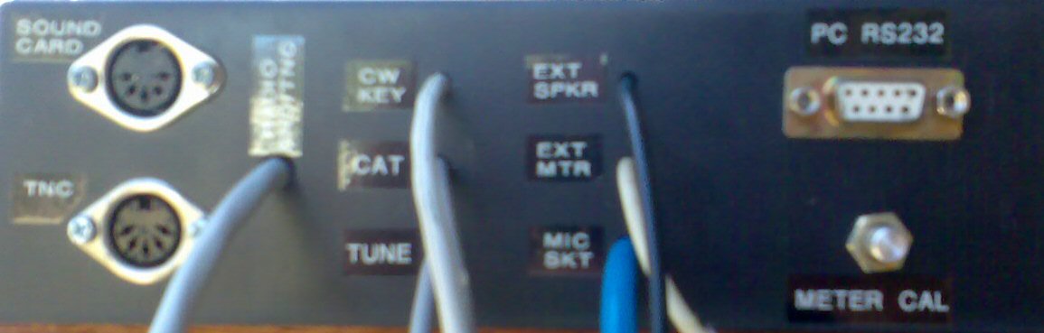

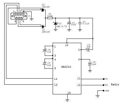
RS232 Communications Cable needed if above circuit is put in a separate box is a pin for pin type. ie. pin 1 to 1, 2 to 2, 3 to 3, through to 9 to 9 etc.
If you are making the cable, minimum would be: Pin 2-2, 3-3, 4-4, 5-5, 6-6, 7-7, 8-8
If you have squelch turned on and no sound is heard until the knob is turned anti-clockwise thereby disabling it, then the following may fix the problem.
Searching the internet found only one other person experiencing the same problem. After a few email exchanges, it was found that we both were using HF with tuners prior to the squelch fault. I was using the FC-30 ATU, and Dennis N8BMB was using a manual tuner. (And, now (Oct 2010) I have received an email from G3ZQI with the problem, including other settings that has changed like mine did.) Is it possibly RF associated with high VSWR while tuning up? If so, then maybe a component has changed value resulting in the final menu value of almost 90 units away from the default CPU value in menu 13 (for example). I'm not sure, but the problem was not fixed by resetting memories or the CPU.
ALSO - You may find that the signal strength on HF is reading incorrectly and the VSWR is also a little out of wack. After fixing the squelch problem, I had to redo all the technical menu settings. For example, setting a S9 reading on the display. Luckily I had another fully working unit I was able to use as a bench mark.
The Fix - by the book
You will need a VHF Signal Generator. (or read below how I did it)
Here is what I had to do.
I don't have a signal generator so I improvised with a hand held and a dummy load.
I pressed the A key for menu 13 and 14 while on low power and whistling into the mic and pressed the A key for menu 15 and 16 while on high power. This did not work, although values were entered about 80 higher than the original value.
WHAT DID WORK was to put the squelch knob up at about 3/4 clockwise and did the same and now I can actually use the squelch quite successfully on all modes / bands.
| Menu Number | Orig Value | New Value |
| 13 | 90 | 178 |
| 14 | 95 | 179 |
| 15 | 4 | 170 |
| 16 | 4 | 170 |
I have since used a signal generator to improve settings, but they remain the same.
Many thanks go to Egor, UN7GDR for the following information...
Service Menus for my FT857D in the Car and in the ShackNote: Menus 13,14,15 and 16 were changed on the Car radio to bring it back to life after the squelch failure on 2m / 70cm. |
|||||
| Menu | Content | Description | Remarks | Car | Shack |
| 001 | HF1RXG | CW 1.825,07 | The higher, the more sensitive the RX is | 200 | 203 |
| 002 | HF2RXG | CW 7.043,55 | 107 | 98 | |
| 003 | HF3RXG | CW 21.070,00 | 198 | 214 | |
| 004 | 50MRXG | CW 50.095,00 | 131 | 148 | |
| 005 | VHFRXG | CW 145.375,00 | 149 | 218 | |
| 006 | UHFRXG | CW 433.425,00 | 90 | 128 | |
| 007 | SSB-S9 | CW 21.070,00 | The higher, the more shown level | 61 | 85 |
| 008 | SSB-FS | CW 21.070,00 | 191 | 54 | |
| 009 | FM-S1 | FM 145.375,00 |
60 = S0 The higher, the higher the S-value is |
71 | 73 |
| 010 | FM-FS | FM 145.375,00 | 99 | 103 | |
| 011 | DISC-L | FM 145.375,00 | Press "A" at test signal given "-3kHz" and "+3kHz" | 53 | 49 |
| 012 | DISC-H | FM 145.375,00 | 80 | 75 | |
| 013 | FM-TH1 | FM 145.375,00 |
open/close level without RX signal (Threshold / Hysteresis) |
175 | 97 |
| 014 | FM-TH2 | FM 145.375,00 | 175 | 92 | |
| 015 | FM-TI1 | FM 145.375,00 |
on RX signal of 3 dBµ (Tight = Enge) |
170 | 5 |
| 016 | FM-TI2 | FM 145.375,00 | 170 | 5 | |
| 017 | VCC | at Ub=13,8V | 138 | 138 | |
| 018 | HF1-IC | CW 1.825,07 | the lower, the more sensitive the protection is | 92 | 101 |
| 019 | HF2-IC | CW 7.043,55 | 84 | 94 | |
| 020 | HF3-IC | CW 21.070,00 | 98 | 121 | |
| 021 | 50M-IC | CW 50.095,00 | 125 | 165 | |
| 022 | VHF-IC | CW 145.375,00 | 75 | 81 | |
| 023 | UHF-IC | CW 433.425,00 | 75 | 81 | |
| 024 | HF1-MAX | CW 1.825,07 | 100W | 172 | 171 |
| 025 | HF1-MID2 | CW 1.825,07 | 50W | 111 | 111 |
| 026 | HF1-MID1 | CW 1.825,07 | 10W | 33 | 33 |
| 027 | HF1-MIN | CW 1.825,07 | 5W | 14 | 15 |
| 028 | HF2-MAX | CW 7.043,55 | 100W | 172 | 172 |
| 029 | HF2-MID2 | CW 7.043,55 | 50W | 109 | 110 |
| 030 | HF2-MID1 | CW 7.043,55 | 10W | 31 | 31 |
| 031 | HF2-MIN | CW 7.043,55 | 5W | 13 | 14 |
| 032 | HF3-MAX | CW 21.070,00 | 100W | 171 | 172 |
| 033 | HF3-MID2 | CW 21.070,00 | 50W | 110 | 110 |
| 034 | HF3-MID1 | CW 21.070,00 | 10W | 31 | 31 |
| 035 | HF3-MIN | CW 21.070,00 | 5W | 13 | 14 |
| 036 | 50M-MAX | CW 50.095,00 | 100W | 158 | 160 |
| 037 | 50M-MID2 | CW 50.095,00 | 50W | 101 | 102 |
| 038 | 50M-MID1 | CW 50.095,00 | 10W | 51 | 51 |
| 039 | 50M-MIN | CW 50.095,00 | 5W | 11 | 12 |
| 040 | VHF-PO-MAX | CW 145.375,00 | 50W | 91 | 93 |
| 041 | VHF-PO-MID2 | CW 145.375,00 | 20W | 44 | 45 |
| 042 | VHF-PO-MIN | CW 145.375,00 | 5W | 7 | 8 |
| 043 | UHF-PO-MAX | CW 433.425,00 | 20W | 123 | 120 |
| 044 | UHF-PO-MIN | CW 433.425,00 | 5W | 15 | 16 |
| 045 | HF1-TXG | USB 1.825,47 | the higher, the higher the TX amplification of driver is (alignment that 5 W FM come out for sure) | 45 | 64 |
| 046 | HF2-TXG | USB 7.043,55 | 48 | 43 | |
| 047 | HF3-TXG | USB 21.070,00 | 49 | 55 | |
| 048 | 50MTXG | USB 50.095,00 | 30 | 31 | |
| 049 | VHFTXG | USB 145.375,00 | 39 | 35 | |
| 050 | UHFTXG | USB 433.425,00 | 62 | 55 | |
| 051 | ALC1-M | USB 21.070,00 |
measured: 180 -> value + 4 dots |
245 | 246 |
| 052 | ALC-M | USB 21.070,00 | 115 | 110 | |
| 053 | HF1-REV-ALC | CW 1.825,07 | the lower, the more sensitive protection and reduction of output power | 65 | 73 |
| 054 | HF2-REV-ALC | CW 7.043,55 | 56 | 64 | |
| 055 | HF3-REV-ALC | CW 21.070,00 | 56 | 61 | |
| 056 | 50M-REV-ALC | CW 50.095,00 | 44 | 53 | |
| 057 | VHF-REV-ALC | CW 145.375,00 | 74 | 50 | |
| 058 | UHF-REV-ALC | CW 433.425,00 | 148 | 131 | |
| 059 | CW-CAR-LEVEL | CW 21.070,00 | 152 | 142 | |
| 060 | AM-CAR-LEVEL | AM 21.070,00 | the lower the higher modulation level | 141 | 130 |
| 061 | DEV-W | FM 145.375,00 | deviation = 5 kHz | 221 | 214 |
| 062 | DEV-N | FMN 145.375,00 | deviation = 2.5 kHz | 113 | 110 |
| 063 | MOD-MTR | FM 145.375,00 | the lower, the more meter level | 201 | 204 |
| 064 | DTMF-DEV | FM 145.375,00 | the higher, the more deviation | 40 | 43 |
| 065 | CTCSS-DEV | FM 145.375,00 | the higher, the more deviation | 230 | 230 |
| 066 | DCS-DEV | FM 145.375,00 |
the higher, the more deviation |
168 | 168 |
| 067 | LSB-CAR-POINT | LSB 21.070,00 | 0 | -10 | |
| 068 | USB-CAR-POINT | USB 21.070,00 | 2 | -7 | |
| 069 | VSWR2 at 10W | CW 14.070,00 | 14 | 20 | |
| 070 | VSWR3 at 10W | CW 14.070,00 | 38 | 45 | |
| 071 | ATAS-TEST | LSB 14.070,00 | |||
| 072 | AMTR-TEST | LSB 14.070,00 | |||
| 073 | HTEMP-Threshold | LSB 14.070,00 | 38 | 38 | |
| 074 | FTEMP-Threshold | LSB 14.070,00 | 102 | 102 |